Terms and Functions
Pulse Width Modulation (PWM)
Pulse Width Modulation is something you will hear talked about quite a lot nowadays. We have a full detailed article about PWM which is worth reading through. In simple terms, PWM is a method used for dimming a monitors backlight whereby the backlight is turned off and on rapidly to simulate lower brightness levels. As you decrease the brightness setting of the screen the “off” periods are increased in length progressively and this in turn leads to a lower luminance output for the display (darker image). The problem with PWM is that on modern LED backlights the rapid turning of the backlight off and on can lead to flickering. Sometimes when the frequency of the PWM is low this might even be visible to some users. In other cases, while it might not be visible the user may still experience unwanted side-effects of its use including eye-strain, headaches, eye fatigue and even nausea.
To overcome this, many manufacturers now actively promote their use of flicker-free backlights and have done away with PWM completely. If you are sensitive to the use of PWM or are just worried about your eye health, we would certainly recommend trying to avoid displays where PWM is used.
Further reading: Pulse Width Modulation Article
Dithering and Frame Rate Control (FRC)
Dithering and Frame Rate Control (FRC) relate to the colour depth of a monitor panel and are technologies used to boost the colours which the matrix can display. For instance TN Film screens are traditionally more economical than other technologies when it comes to colour depth. In fact, they only display 64 red, 64 blue and 64 true green shades by default through pixel rotations. The maximum amount of colours achievable from liquid crystal rotation alone is 262,144. In order to reach 16 million colours and above, panel manufacturers commonly use two technologies: Dithering and Frame Rate Control (FRC). These terms are often interchanged, but strictly can mean different things.
- Spatial Dithering – This dithering method involves assigning appropriate colour values from the available colour palette to close-by pixels in such a way that it gives the impression of a new colour tone which otherwise could not have been created at all. In doing so, there complex mappings according to which the ground colours are mutually assigned, otherwise it could result in colour noise / dithering noise. Dithering can be used to allow 6-Bit panels, like TN Film, to show 16.2 million perceived colours. This can however sometimes be detectable to the user, and can result in chessboard like patterns being visible in some cases. Spatial dithering is rarely used in the modern market and instead Frame Rate Control is more widely utilised.
- Frame Rate Control / Temporal Dithering – The other method is Frame-Rate-Control (FRC), also referred to sometimes as temporal dithering. This works by combining four colour frames as a sequence in time, resulting in perceived mixture. In basic terms, it involves flashing between two colour tones rapidly to give the impression of a third tone, not normally available in the palette. This allows a total of 16.2 reproducible million colours in 6-bit TN Film matrices. FRC is also used to enhance the colour depth of 8-bit panels, boosting them from their standard 16.7 million colours to 1.07 billion in the case of “10-bit” panels (8-bit + FRC). There are a number of FRC algorithms which vary in their effectiveness. Sometimes, a twinkling artefact can be seen, particularly in darker shades, which is a side affect of such technologies.
Interpolation / Scaling of Resolution
While TFT screens are best run at their native resolutions, it is possible to run them at lower resolutions if need be. In doing so the screen must interpolate the image from below the native resolution, leading commonly to some loss in image clarity and sharpness as the image is stretched across pixels. In office use this can be a problem and can look quite poor, but in gaming, it is generally not so much of a problem. The ability of a TFT to interpolate the image depends on the particular panel and scaler used, and some manufacturers have been able to improve the ability of their panels to run outside the native resolution. Generally though it is not recommended to run outside the native resolution on a TFT if you can help it. Where resolutions are very high (e.g. Ultra HD / 4K) then you will still want to run the display at the full native resolution, but enabled operating system scaling to make everything easier to see.
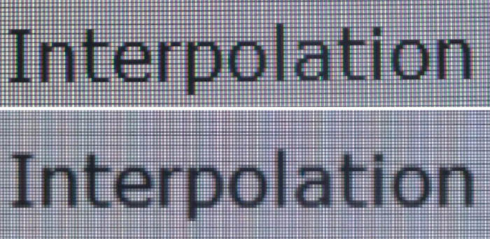
Above: photo of text at 2560 x 1440 (top) and 1920 x 1080 (bottom) as an example of interpolation
Where screens are having to handle lower resolutions, the image will normally be interpolated and stretched to fill the screen completely. This can cause problems if your source content does not match the aspect ratio of the screen. One way manufacturers can get round this is with the use of aspect ratio retention methods including what is commonly referred to as 1:1 pixel mapping. This aspect ratio retention can be carried out by the screen in some cases where the options are available, or if not, you can normally achieve it via your graphics card control panel.
Aspect Ratio Control and 1:1 Pixel Mapping

This feature refers to the screens ability to maintain an aspect ratio of a source image at the hardware level. For instance, if you tried to play a 4:3 aspect game on a 16:10 format display, the image would normally be stretched to fill the screen, stretching the aspect ratio horizontally. However, if the hardware is capable of maintaining the aspect ratio, the screen can display the source in it’s normal 4:3 ratio, and will add black borders along each side.
This aspect ratio retention can be achieved in two ways. The most reliable and easy to use is through the hardware (monitor) itself and normally involves the availability of preset modes in the OSD. There are often differing options available for aspect ratio control, including:
- “fill” the screen ignoring any aspect ratio differences between source and display. A 4:3 source would be stretched to fill the screen regardless for example.
- “aspect” or “auto” is used to maintain whatever aspect ratio is sent by the source, but interpolate the image to fill as much of the screen as possible. This would result in black borders along the right and left hand sides on a WS format screen displaying a 4:3 source for example.
- 4:3, 5:4, 16:9 and 16:10 – often modes are provided to specially control and maintain a defined source aspect ratio such as these. Keep in mind the native aspect ratio of the screen as well.
- “1:1 pixel mapping” – this is used to literally map the exact number of pixels specified in the source resolution to pixels on the screen. For instance a 1024 x 768 source resolution would be displayed on a 1920 x 1200 resolution monitor, only using the pixels required and would not be interpolated or stretched. This would result in black borders on all sides of the image. This would be like using a smaller screen within the larger screen and is handy for those wanting to run games at lower resolutions but without losing image quality through interpolation.
The other option for aspect ratio retention is through software. NVIDIA and AMD display drivers for instance can achieve similar settings to above quite easily. However, results can be a little more variable and difficult to achieve. They are of course no use if you are using an external device such as a DVD/Blu-ray player or games console as they are not normally able to control the aspect ratio themselves and would need to rely on the screen to support it at a hardware level.
Backlight Leakage
Backlight leakage refers to the problem some screens exhibit where in a darkly lit room, and with a dark image on the screen, you can clearly see areas particularly around the edges where the backlight shines through. This is a problem with the manufacturing stage and quality of the monitor build and can also sometimes be influenced by transportation and storage. A lot of panels will show slightly uneven backlighting, with perhaps a little light noticeable at the edges of the screen or in the corners. Where it is minor, and only visible on very specific (and unrealistic) test situations it is probably not worth worrying about. Also consider that a screen might need some “bedding in” time to settle in your office before you test this kind of thing. Panel uniformity can vary from one screen to the next and from sample to sample, it is very hard to predict. Where backlight bleed is severe or very distracting, a return to the retailer or manufacturer is suggested.
Note: if you want to test your own screen for backlight bleed and uniformity problems at any point you need to ensure you have suitable testing conditions. Set the monitor to a sensible day to day brightness level, preferably as close to 120 cd/m2 as you can get it (our tests are once the screen is calibrated to this luminance). Don’t just take a photo at the default brightness which is almost always far too high and not a realistic usage condition. You need to take the photo from about 1.5 – 2m back to avoid capturing viewing angle characteristics, especially on IPS-type panels where off-angle glow can come in to play easily. Photos should be taken in a darkened room at a shutter speed which captures what you see reliably and doesn’t over-expose the image. A shutter speed of 1/8 second will probably be suitable for this.
On IPS-type panels a characteristic IPS-glow is commonly mistaken for backlight bleed. See the section on IPS-glow for more information.
IPS-glow

On modern IPS panels when viewing a black image there is typically a characteristic white glow when viewed from an angle, commonly referred to as “IPS-glow”. This is common on most modern IPS-type panels and can be distracting to some users. The level of glow shown here is pretty typical of a modern IPS-type panel. If you view dark content from a normal head-on viewing position, you can actually see this glow slightly as your eyes look towards the edges of the screen if it is of a large size. The wider the screen and the bigger it is, the more likely you are to see some glow from your normal viewing position as you glance towards the edges. A curve to the screen can help reduce this a little as the angle between your eyes and the edges is reduced a little. Some people may find this IPS-glow problematic if they are working with a lot of dark content or solid colour patterns. In normal day to day uses, office work, movies and games you probably wouldn’t really notice this unless you were viewing darker content. If you move your viewing position back, which is probably likely for movies and games, the effect reduces as you do not have such an angle from your eye position to the screen edges.
This is one area where TN Film panel technology is actually better than IPS-type for viewing angles, as there is far less pale glow from an angle on dark content. For dark room conditions, and a lot of dark content some people might prefer to live with the more restrictive viewing angles and less glow of the TN Film panel. Others might want to use the screen for more all-round uses and prefer the IPS panel. It’s down to preference really and your individual uses.

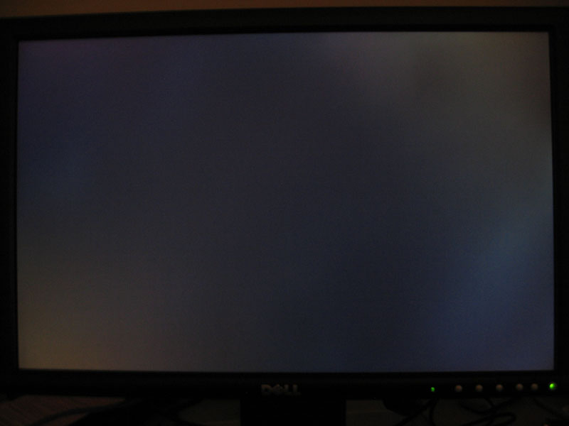
We want to make a point at this stage relating to IPS glow. The above image shows the corners of the screen as observed from a central viewing position, at a normal viewing distance of a couple of feet from the screen. As you look towards the corners of the screen you can see a glow and pale areas on the dark content. This is not backlight bleed! We see many reports of users who mistake IPS glow which is a panel characteristic, for backlight bleed which is a build quality issue. This glow in the corners is caused by your angle of vision when viewing the screen and is because of the pixel structure on the IPS panel. If you view the screen from even wider angles (like the image shown above it) the glow becomes more white and pale. This IPS glow is a “feature” of nearly every IPS-type panel on the market, so as a buyer you should be expecting it. It’s not grounds for a return of the screen as a fault when it is just a feature of the panel technology. The bigger the screen, and the wider the field of view, the more obvious this glowing from the corners will be. On a 34″ ultra-wide screen for instance there are very wide fields of view and so you will notice it when sat up close to the screen and viewing dark content.

If you move your viewing position back a metre or so and view that side of the screen head on as shown above, the glow has disappeared. You can tell there’s barely any clouding or bleed from the backlight in these corners. So what was previously thought of as bleed, actually isn’t at all.
Banding
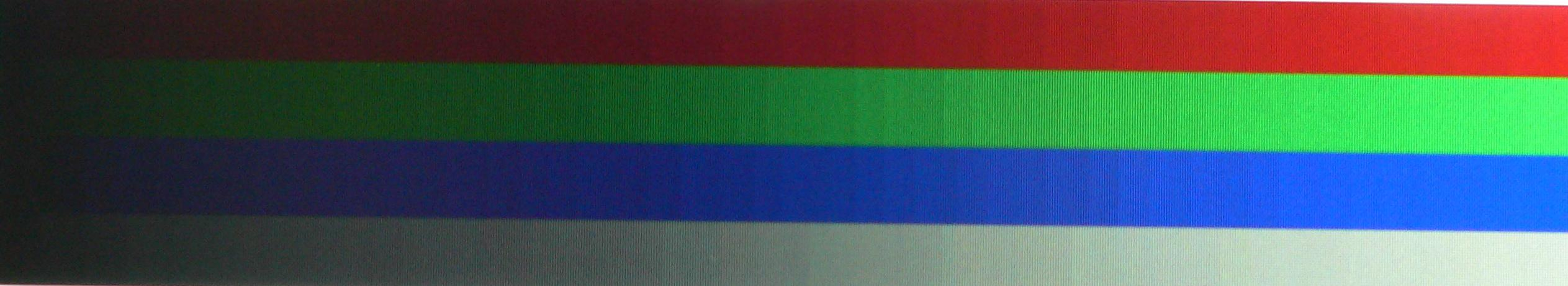
Banding is an issue which you can sometimes spot on a monitor, and involves blocking and gradation of colours to a considerable level. This is most evident when viewing colour gradients, and rather than the colours showing a gradual change in shade as they should, the image appears as blocks with clearly defined steps. A certain degree of gradation in a gradient image can be expected from many monitors, despite the fact that in an ideal world, the gradient would be smooth and all transitions would be transparent. However, it is in the cases where the gradation is more noticeable that it results in what is popularly referred to as “banding”.
Some users think that striped gradients are due to the use of 6-bit matrixes instead of 8-bit ones, but this is not exactly true. The lower colour depth of the matrix may indeed lead to stripes in gradients if the Frame Rate Control is poorly implemented (this is the technology that emulates 16 million colours while the matrix itself is only capable of displaying ~262,000), but the real reason is usually different. Before outputting the image on the screen, the monitor performs a series of calculations and transformations: colour temperature correction, gamma compensation, contrast correction, etc. If the accuracy of those calculations is low, you see striped gradients. The matrix’s colour depth has nothing to do with it. Even an “honest” 8-bit matrix cannot guarantee that the monitor will correctly process the data before sending them to the matrix. Some models will offer technologies which have higher bit internal processing (commonly 10-bit or 12-bit for example) along with higher bit LUT to help provide wider colour palettes and better processing. This can help minimise and avoid banding issues on gradients.
Some monitors have made banding rather infamous and so many potential buyers now cite this as an important test of a screen, and something which can really separate the good from the bad. A lot of this is quite exaggerated however, with far too much concern about even slight gradation across colour gradients. The early releases of the Dell 2xx7 series were a classic example of where colour banding became a concern. The early releases did show some pretty bad banding, which was promptly fixed by Dell with firmware upgrades. However, it has resulted in many users criticising displays for even slight gradation, and not really considering whether it is really an issue in real use. For the majority of users, it would probably not be an issue in practice, and you’d probably be hard pressed to see any adverse affects of this issue in anything other than colour gradient tests. I would advise caution about the talk of banding on displays, and consider whether there is really as much of an issue as some people make out.
Screen Door
The Screen Door effect is so called because sometimes it is possible to clearly see the individual pixels in a panel and the gaps between them. This is quite rare, but can be distracting if you are using a TFT up close. It may be more apparent where pixel pitch is large (e.g. a large screen with a relatively low native resolution / number of pixels in the matrix).
Input Lag

Input lag is described as the lag between the output from a graphics card and the image which is displayed on the screen you are using. For LCD screens this should not be confused with pixel response time which describes the speed at which a pixel can change from one orientation to another. Pixel response times impact aspects such as motion blur and ghosting in moving images. On the other hand input lag is a delay between what is sent to the monitor, and what you actually see. This can have impacts particularly in gaming where if the screen is lagging at all, it can have adverse affects on first person shooter games and the likes where every millisecond counts. Lag is more about the ‘feel’ of delay.
Input lag is sometimes categorised in two ways which can make things a little confusing. One way to describe input lag is to talk about the raw signal processing delay introduced by the electronics of the screen. In some cases this can be measured accurately using an oscilloscope system. However while that might strictly be the “input lag” of the screen it doesn’t account for the overall lag of the display experienced by the user. It is the overall “display lag” which is also important to users and is really the number most regularly referred to as “input lag”. The display lag would be a combination of the signal processing lag and an element of the pixel response times. This overall display lag would then be that seen by the user when comparing against a CRT for instance.
The level of lag really depends on the TFT display, and is controlled by many signal processing factors including, but not limited to the internal electronics and scaling chips. Some manufacturers even take measures to help reduce this, providing modes which bypass scaler chips and options which reduce the input lag. These are often reserved for gamer-orientated screens but the results can be quite noticeable in some cases. Where NVIDIA G-sync modules are used you will tend to see very low levels of lag as well, as the screen does not have a scaler present.
In practice, input lag is unlikely to affect too many general users. There is quite a lot of fuss made about it on forums, but in reality I would doubt many people will see any real issues on the majority of displays. Some professional gamers who rely on being able to match their key presses and mouse movements with what is shown on the screen might suffer in some cases, so it is something to be wary of. Generally though, we would avoid worrying too much about this issue for most average uses.
Further Reading: Input Lag Measurement Techniques
Look Up Table (LUT)
If you want a full understanding of what a Look Up Table is I’d recommend reading here on Wikipedia. For the sake of keeping this more simple, in the context of monitors we commonly talk about two types of LUT which ultimately communicate with one another to produce the image seen on your screen.
- A graphics card LUT – This is the LUT relating only to the graphics card driving your monitor. In crude terms, it controls the colours, and output of the graphics card. During processes such as calibration, this LUT can be adjusted and this can help improve colour accuracy and other settings such as colour temperature and gamma. These corrections and settings can be saved and profiled to ensure lasting results.
- A monitor LUT – All monitors will have a LUT which translates the data sent from the graphics card to it and controls the display of the image. Some higher end monitors allow you to adjust the settings in the screen itself, and this is often referred to as a hardware calibrated LUT. Again calibration can adjust the settings of the screen, but this time they are saved within the screen itself for improved accuracy and stability. Hardware calibration is usually reserved for high end professional-grade screens due to its cost to implement.
3D LUT for Better Additive Colour Mixture
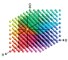
Whereas a typical 1D LUT adjusts colour on separate tables for each red, green, and blue, a 3D LUT accomplishes this on a single, mixed-colour cubic table. A 3D LUT improves the monitor’s additive colour mixture (combination of RGB), a key factor in its ability to display neutral grey tones.
ClearType
Cleartype was introduced by Microsoft for use with LCD displays to make fonts more rounded and less jagged. This is effectively a filter used to blur the fonts a little which some people prefer the look of. This can vary from one TFT to another, and it is easy enough to turn on and off to allow you to decide which you prefer. Microsoft’s article about the Cleartype filter can be found here:
Further info: Microsoft
Burn-In / Image Retention
Image burn in was traditionally a problem with CRT displays, where prolonged images on the screen could leave a ghost image behind after it has changed. This was a problem with older CRT displays and was the reason for the introduction of screen savers. With TFT’s this is not really a major problem as the image cannot be burnt into the screen by the cathode ray gun, as the pixels all operate individually. Some screens can very occasionally show some lasting imprint of an image if the same picture is left on the screen for long periods of time, but it is generally not permanent. This can often be easily solved by looking at some fast moving scenes or gaming. For the sake of electricity more than anything else though, it is probably easiest to use the power settings on your PC to turn the screen off when not in use.
Dead Pixels
One of the main concerns people have when buying a TFT relates to the problem of dead pixels. Pixels can sometimes be ‘dead’ (stuck on black or white). Sometimes the sub pixels which make up the pixel can be dead which leaves the pixel looking red, green or blue. Sometimes the sub pixels can be ‘lazy’ and with a bit of luck can come back to life.
Dead pixels / sub pixels defects are normally caused during the manufacturing stage, and it is very rare for a panel to generate a pixel fault at a later stage unless you have a tendency to prod the screen. Nowadays, manufacturing levels are very good and it is quite rare for a pixel to be ‘dead’, and you will see some manufacturers like Samsung and ViewSonic for instance, offering zero dead pixel policies. Dead sub pixels are still a problem, and the policy will not cover these in most cases. Dead pixels are not really considered a fault with a TFT monitor and you will need to consider this before purchasing. Refer to the manufacturer to find out what their dead pixel policy is.
Further Reading: What’s The Situation With Dead Pixels?
On Screen Display (OSD)

The OSD refers to the “On Screen Display” available on nearly all TFT monitors. This allows the user to change settings ranging from brightness, contrast and colour levels (typically RGB) to more advanced features like aspect ratio and monitor preset modes instance. One thing to note is that some features like contrast, phase and pixel clock are only available when using the VGA (analogue) interface and become greyed out when using the DVI (digital interface) as they are no longer required. Proper configuration of a monitor requires RGB levels to be altered and brightness and contrast to be set correctly. More advanced features are often accessible and modern OSD often offer a wealth of selections. Some OSD also offer factory menus and information about the screen or panel being used which can be particularly useful for the enthusiast.
HDCP Support

High-bandwidth Digital Content Protection (HDCP) is a form of Digital Rights Management (DRM) developed by Intel Corporation to control digital audio and video content as it travels across Digital Visual Interface (DVI) or High-Definition Multimedia Interface (HDMI) connections. The specification is proprietary, and creating an implementation of HDCP requires a license.
HDCP’s main target is to prevent transmission of non-encrypted high definition content. In basic terms source material (HD-DVD, BluRay, Next Gen Video Games etc) will be encrypted with HDCP protection. In order to view / use these sources you will need each step in the ‘chain’ to have support for this protection technique. This includes graphics cards in PC’s, DVD players and ultimately (and where we are interested in), the monitor / display device. If all these steps do not have support for HDCP, any encrypted material will have problems playing, typically being reduced to a much lower resolution, showing “not supported” type messages, or not showing any image at all.
HDCP functions over digital interfaces only; and so DVI and HDMI ports are those most affected at present. For a monitor or TV to be truly HD compliant, it must offer HDCP compatibility. Many modern displays do offer this support, but bare in mind they would need digital interfaces to offer this. You may want to consider whether a monitor has HDCP support or not when making your decision, since it may well have an impact on your use in the future. While it was thought that HDCP would not be implemented for many years, it seems it may well be sooner than we had expected. See the below links for further information.
Ergonomics – Tilt / Height/Swivel/Rotate

Many screens today have the added functionality of height, pivot, rotate or tilt functions, or sometimes more than one of these. These are provided depending on the stand used and often dependent on the size of the screen. To provide a versatile stand with a wide range of adjustments can add additional cost to the screen and so on some models they are left off.
- Tilt – allows the screen to tilt backwards and forwards to achieve a comfortable angle for viewing. Tilt is provided on nearly all monitors, even on the most basic stands
- Height – allows for an adjustment of the screen up and down and is useful to achieve a comfortable position for different users, desk positions etc. Height adjustment is not always provided by stands as it usually results in a higher production costs
- Swivel – is a function allowing the screen to ‘swing’ side to side to allow you to turn the screen to face different users or viewing positions.
- Rotate – is a function allowing you to flip the screen between landscape and portrait modes. This might be left off some larger screens as it loses its practical uses. Where provided the screen often comes coupled with software which automatically rotates your desktop on demand. This can also easily be achieved with most graphics card software. This can be handy for office and photo work in particular.
Be careful of screens with limited tilt and height adjustments, as they might be restrictive when it comes to aligning them to your line of sight. The use of some features, particularly rotate, becomes a little questionable on the larger screens such as >24″ models, but some may still find them useful and an attractive buying point.
VESA Compatibility
It is possible to detach the stand from some TFT models and instead mount them to a swinging arm on a wall or desk. If this is something you might wish to do, look for TFT’s which specify compatibility with VESA mounts. These can provide improved alignment of a monitor and easier use depending on your needs.
DDC/CI Compliance
One of the requirements for a Windows Vista when it was released (and kept in later operating systems) was that a compatible monitor is DDC/CI (Display Data Channel Command Interface) compliant. This provides full bidirectional communication between host (PC) and display. Through DDC/CI support, user can use appropriate software to adjust the monitor instead of using the monitor control keys.
Picture In Picture (PiP) and Picture By Picture (PbP)
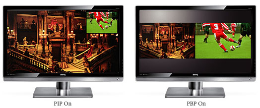
These terms are used where a monitor will support displaying multiple inputs on the screen at the same time. For instance you may be able to display the DVI input as well as the HDMI input at the same time. The method for showing two different inputs at the same time can commonly be achieved using PiP or PbP as demonstrated in the image above. You can normally resize and re-position the different images to suit.
Colour Reproduction
Colour reproduction is related to the ability of a panel to produce the colours desired. Typically, the colour reproduction is measured by reviewers using a hardware colorimeter device and a top end software package. They are recorded on graphs similar to this example (on the right):
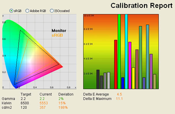
This graph on the right shows the difference between the desired color shade and the one actually displayed. Basically, the lower these bars down the Y-axis, the better, in terms of colour accuracy. For reference, LaCie (who produce this specific software) describe the DeltaE readings as:
- If DeltaE >3, the color displayed is significantly different from the theoretical one, meaning that the difference will be perceptible to the viewer.
- If DeltaE <2, LaCie considers the calibration a success; there remains a slight difference, but it is barely undetectable.
- If DeltaE < 1, the color fidelity is excellent.
See our reviews for further information about colour accuracy, but it is worth noting that colour accuracy will vary from one screen to another, often varies between different panel technologies, and will vary between default factory settings and a calibrated profile. As a note, the example shown above has very poor colour reproduction accuracy.
Contrast Stability
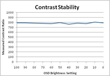
This curve indicates the contrast value measured at a given brightness adjustment on the OSD. In theory, brightness and contrast are two independent parameters, and good contrast is a requirement regardless of the brightness adjustment. Unfortunately, such is not the case in practice. The brightness adjustment is shown on the X-axis, contrast on the Y-axis, and in theory this should be fairly even across the OSD brightness adjustment range (but isn’t always!)
Panel Uniformity
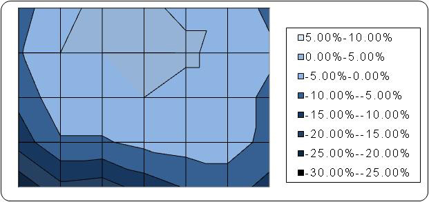
Again, some reviewers like ourselves measure the uniformity of a screen. This is useful for considering the uniformity of the panels lighting, and relates to backlight bleeding sometimes when uniformity is particularly bad. Measurements are taken across the screen and compared with a given reference value as measured in the centre of the screen. The deviance from this reference point is then provided as a percentage, showing how the luminance varies across the screen.