Pulse Width Modulation (PWM)
Originally published 16 February 2012, last updated 17 March 2015. With thanks for input and content to Shea Hagstrom

Introduction
The wide range of conditions over which LCD monitors are used means that it is desirable to produce displays whose luminance (brightness) can be altered to match both bright and dim environments. This allows a user to set the screen to a comfortable level of brightness depending on their working conditions and ambient lighting. Manufacturers will normally quote a maximum brightness figure in their display specification, but it is also important to consider the lower range of adjustments possible from the screen as you would probably never want to use it at its highest setting. Indeed with specs often ranging up to 500 cd/m2, you will certainly need to use the screen at something a little less harsh on the eyes. As a reminder, we test the full range of backlight adjustments and the corresponding brightness values during each of our reviews. During our calibration process as well we try to adjust the screen to a setting of 120 cd/m2 which is considered the recommended luminance for an LCD monitor in normal lighting conditions. This process helps to give you an idea of what adjustments you need to make to the screen in order to return a luminance which you might actually want to use day to day.
Changing the display luminance is achieved by reducing the total light output for both CCFL- and LED-based backlights. By far the most prevalent technique for dimming the backlight is called Pulse Width Modulation (PWM), which has been in use for many years in desktop and laptop displays. However, this technique is not without some issues and the introduction of displays with high brightness levels and the popularisation of LED backlights has made the side-effects of PWM more visible than before, and in some cases may be a source of visible flicker, eyestrain, eye fatigue, headaches and other associated issues for people sensitive to it. This article is not intended to alarm, but is intended to show how PWM works and why it is used, as well as how to test a display to see its effects more clearly. We will also take a look at the methods some manufacturers are now adopting to address these concerns and provide flicker-free backlights instead. As awareness grows, more and more manufacturers are focusing on eye health with their monitor ranges.
What is PWM?
Pulse Width Modulation (PWM) is one method of reducing the perceived luminance in displays, which it achieves by cycling the backlight on and off very rapidly, at a frequency you can’t necessary detect with the naked eye, but which could lead to eye issues, headaches etc. This method generally means that at 100% brightness a constant voltage is applied to the backlight and it is continuously lit. As you lower the brightness control the perceived luminance for the user reduces due to a number of possible controlling factors:

1) Frequency – The backlight is cycled on and off very rapidly, and this cycling typically occurs at a fixed frequency (in Hz). How fast this cycling occurs can impact whether flicker is visible or perceivable to the user, with higher frequencies being potentially less problematic. PWM has been known to operate at low frequencies of 180 – 240Hz for example which are likely to be more problematic than higher frequencies ranging up in to the Kilohertz range (e.g. 18,000Hz).
2) Modulation – The modulation of the cycling has an impact on the perceived brightness, and this describes the difference between the luminance in an “on” and in an “off” state. In some examples the backlight is completely turned off during the cycle so it is literally being turned on/off rapidly across the full brightness adjustment range. In those examples the luminance output is controlled really by the duty cycle only (see point 3). In other examples the backlight is not always being completely turned off but rather the voltage applied to the backlight is being rapidly alternated, resulting in less extreme differences between the on and off states. Often this modulation will be narrow in the high brightness range of the display, but as you reduce further, the modulation becomes wider until it reaches a point where the backlight is being switched completely off. From there, the change in the duty cycle (point 3) controls the further changes in the luminance output.
3) Duty Cycle – The fraction of each cycle for which the backlight is in an “on” state is called the duty cycle. By altering this duty cycle the total light output of the backlight can be changed. As you reduce the brightness to reach a lower luminance, the duty cycle becomes progressively shorter, and the time for which the backlight is on becomes shorter, while the time for which it is off is longer. This technique works visually since cycling the backlight on and off sufficiently fast means the user cannot see this flickering, because it lies above their flicker-fusion threshold (more on this later).
 |  |  |
| 90% duty cycle | 50% duty cycle | 10% duty cycle |
Above we can see graphs of a backlight’s output using “ideal” PWM for several cycles. The maximum output of this backlight in the example is 100 cd/m2, and the perceived luminance for the 90%, 50% and 10% cases are: 90, 50 and 10 cd/m2 respectively. The modulation percentage is the ratio between the minimum and maximum luminance during the cycle, and is 100% here, so it is being completely turned on and off. Note that during the duty cycle the backlight is at its maximum luminance.
 |  |  |
| 90% continuous | 50% continuous | 10% continuous |
The analogue (non-PWM) graphs corresponding to these perceived luminance levels would appear as shown below. In this case there is no modulation. This is the method used for flicker-free backlights which we will discuss more a little later.
Why PWM is Used
The main reasons for the use of PWM is that it is simple to implement, requiring only that the backlight can be switched on and off rapidly, and also gives a large range of possible luminance.
CCFL backlights can be dimmed by reducing the current through the bulb, but only by about a factor of 2 because of their strict current and voltage requirements. This leaves PWM as the only simple method of achieving a large range of luminance. A CCFL bulb is in fact normally driven by the inverter to cycle on and off at a rate in the 10’s of kilohertz and well outside the range of flicker visible to humans. However, the PWM cycling typically occurs at a much lower frequency, around 175Hz, which can produce artefacts visible to humans.
The luminance of LED backlights can be adjusted greatly by altering the current passing through them, though this has the effect of altering the colour temperature slightly. This analogue approach to LED luminance is also undesirable since the accompanying circuits must take into account the heat generated by the LED’s. LED’s heat up when on, which reduces their resistance and further increases the current flowing through them. This can quickly lead to runaway current use in very high-brightness LED’s and cause them to burn out. Using PWM the current can be forced to hold a constant value during the duty cycle, meaning the colour temperature is always the same and current overloads are not a problem.
Side Effects of PWM
While PWM is attractive to hardware makers for the reasons outlined above, it can also introduce distracting visual effects if not used carefully. Flicker from LED backlights is typically much more visible than for older CCFL backlights at the same duty cycle because the LED’s are able to switch on and off much faster, and do not continue to “glow” after the power is cut off. This means that where the CCFL backlight showed rather smooth luminance variation, the LED version shows sharper transitions between on and off states. This is why more recently the subject of PWM has cropped up online and in reviews, since more and more displays are moving to W-LED backlighting units now.
Where the effect of flicker can really come into play is any time the user’s eyes are moving. Under constant illumination with no flickering (e.g. sunlight) the image is smoothly blurred and is how we normally perceive motion. However, when combined with a light source using PWM several discrete afterimages of the screen may be perceived simultaneously and reduce readability and the ability of the eyes to lock onto objects. From the earlier analysis of the CCFL backlighting we know that false colour may be introduced as well, even when the original image is monochromatic. Below are shown examples of how text might appear while the eyes are moving horizontally under different backlights.
| Original |  |
| Without PWM |  |
| CCFL PWM |  |
| LED PWM |  |
It is important to remember that this is entirely due to the backlight, and the display itself is showing a static image. Often it is said that humans cannot see more than 24 frames per second (fps), which is not true and actually corresponds to the approximate frame rate needed to perceive continuous motion. In fact, while the eyes are moving (such as when reading) it is possible to see the effects of flicker at several hundred hertz. The ability to observe flicker varies greatly between individuals, and even depends on where a user is looking since peripheral vision is most sensitive.
So how fast is PWM cycling backlights on and off? This seems to depend on the backlight type used, with CCFL-based backlights nearly all cycling at 175Hz or 175 times per second. LED backlights have been reported typically running from 180 – 420Hz, with those at the lower end flickering much more visibly. Some have even faster frequencies of >2000Hz so it really can vary. While this might seem too fast to be visible, keep in mind that 175Hz is not much faster than the 100-120Hz flicker observed in lights connected directly to the mains power.
100-120Hz flickering of fluorescent lights has in fact been linked to symptoms such as severe eye strain and headaches in a portion of the population, which is why high-frequency ballast circuits were developed that provide almost continuous output. Using PWM at low frequencies negates the advantages of using these better ballasts in backlights because it turns an almost constant light source back into one that flickers. An additional consideration is that poor quality or defective ballasts in fluorescent backlights can produce audible noise. In many cases this is exacerbated when PWM is introduced since the electronics are now dealing with an additional frequency at which power usage is changing.
It is also important to distinguish the difference between flicker in CRT displays and CCFL and LED backlit TFT displays. While a CRT may flicker as low as 60Hz, only a small strip is illuminated at any time as the electron gun scans from top to bottom. With CCFL and LED backlit TFT displays the entire screen surface illuminates at once, meaning much more light is emitted over a short time. This can be more distracting than in CRTs in some cases, especially if short duty cycles are used.
The flicker itself in display backlights may be subtle and not easily perceptible for some people, but the natural variation in human vision seems to make it clearly visible to others. With the use of high-brightness LED’s on the rise it is becoming increasingly necessary to use short PWM duty cycles to control brightness, making flicker more of a problem. With users spending many hours every day looking at their monitors, shouldn’t we consider the long term effects of both perceptible and imperceptible flicker?
Reducing the Effects of PWM and Flicker Free Backlights
If you find PWM backlight flickering distracting or just want to see if reducing it makes reading on a monitor easier, I’d encourage you to try the following: Turn the brightness of your monitor up to maximum and disable any automatic brightness adjustments. Now use the colour correction available in your video card drivers or calibration device to reduce the brightness to normal levels (usually by adjusting the contrast slider). This will reduce the luminance and contrast of your monitor while leaving the backlight on as much as possible during PWM cycles. While not a long-term solution for most due to the decreased contrast, this technique can help to discover if a reduction in PWM usage is helpful.
A much better method of course would be to purchase a display not relying on PWM for dimming, or at least one which uses a much higher cycling frequency. Few manufacturers seem to have implemented PWM at frequencies that would limit visible artefacts (well above 500Hz for CCFL and above 2000 Hz for LED). Additionally, some displays using PWM do not use a 100% duty cycle even at full brightness, meaning they will always produce flicker. Several LED-based displays may in fact be currently available which do not use PWM, but until backlight frequency and modulation become listed in specifications it will be necessary to see the display in person. Some manufacturers promote “flicker free” monitors in their range (BenQ, Acer for example) which are designed to not use PWM at all and instead use a Direct Current (DC) method of backlight dimming. Other manufacturers such as Eizo talk about flicker free backlights but also list a hybrid solution for their backlight dimming, where PWM is used for some of the brightness adjustment range at the lower end. In fact it seems an increasingly common practice for a screen to be PWM free down to a certain point, and then fro PWM to be used to really drive down the minimum luminance from there.
Testing and Interpretation
An easy method of measuring the PWM frequency of a backlight would be ideal, and luckily it can be done using only a camera which allows manual control of the shutter speed. This can quickly and easily identify PWM frequencies in the lower range, but may not be suitable for high frequency PWM. It should be able to detect PWM up to at least 500Hz though, but anything above that may look like a solid block, suggesting no use of PWM, when in fact it might be just using a higher frequency. Further more complex methods such as our oscilloscope setup would be needed to validate flicker-free status for definite.
Instructions are as follows:
Capture:
- Set the monitor to the desired settings for testing.
- (Optional) Set the camera white balance by getting a reading off the screen while displaying only white. If not possible, then manually set the white balance to about 6000K.
- Display a single vertical thin white line on a black background on the monitor (1-3 pixels wide should be fine). The image should be the only thing visible. Here is an example you may wish to save and use, show it full screen on your monitor.
- Set the camera to use a shutter speed of 1/2 to 1/25 of a second. You may need to set the ISO sensitivity and aperture in order to capture enough light. Make sure the line is in focus at the distance you are holding it (lock the focus if needed).
- Hold the camera about 2 feet in front of the monitor and perpendicular to (looking straight at) the front. Press the shutter button as you slowly move it horizontally across the screen (remaining perpendicular). You may need to experiment with moving the camera at different speeds.
Post-processing:
- Adjust the captured image brightness so that the pattern is easily visible.
- Count the number of cycles visible in the captured image.
- Multiply this count by the inverse of the shutter speed. For example, if using a shutter speed of 1/25 of a second and 7 cycles are counted, then the number of cycles per second is 25 * 7 = 175Hz. This is the backlight cycle frequency.
 |  |  |
| Test image | Photograph | Cropped and cleaned-up |
What we are doing with this technique is turning a temporal effect into a spatial one by moving the camera during capture. The only significant source of light during the image capture is the thin line on the display, which is exposed onto consecutive columns on the sensor. If the backlight is flickering, different columns will have different brightness or colour values determined by the backlight at the time it was exposed.
A common problem when first attempting this technique is that the image is too dark. This can be mitigated by using a larger camera aperture (lower f/number) or increasing the ISO value. The shutter speed is not a factor in the exposure since we are using it only to control the total exposure time. The brightness of the image can also be adjusted by changing the speed at which the camera is moved, with a fast speed giving a darker image and more temporal resolution and a slow speed a brighter image with lower resolution. Another problem encountered is unevenly-spaced cycles in the final image, which is caused by the camera changing speed during exposure. Continuing to move the camera before and after the exposure helps to steady this. An image which looks particularly smooth may be due to it being out of focus. This can sometimes be helped by pressing the shutter button halfway to focus on the line target, then proceeding as normal.
| Problem | Looks like | Solution |
| Image too dark |  | Increase exposure after capture. Use larger lens aperture. Move camera more slowly. |
| Uneven spacing |  | Move camera at constant speed. Try to keep camera moving before and after exposure. |
| Image out of focus |  | Lock focus. Pre-focus by pressing shutter halfway. Ensure camera is perpendicular to screen. |
Depending on the monitor several additional effects may be visible. CCFL-based backlights often show different colours at the start and end of each cycle, which means the phosphors used respond at different rates. LED-based backlights often use a higher cycling frequency than CCFL-based, and more rapid camera movement may be needed to easily see them. Dark stripes between cycles mean that the PWM duty cycle has been reduced to such an extent that no light is emitted for part of the cycles.
The following are examples of using this method:

Advanced Oscilloscope Tests
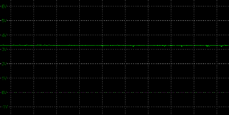
Using our oscilloscope and photosensor equipment it is possible to measure the PWM frequency and patterns far more accurately. While the above photo method is certainly suitable for a casual user, an oscilloscope can reveal more detail about the PWM operation and will be featured in all our reviews moving forward. We measure the luminance output of the screen at brightness settings of 100, 50 and 0%. This allows us to easily identify the backlight dimming technique, and if PWM is being used we can work out its frequency and comment on modulation, duty cycle etc.
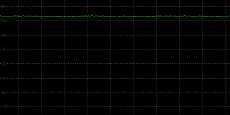 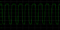 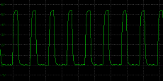 Brightness setting 100% 50% 0% |
| Asus PA248Q – W-LED backlight. At 100% brightness we see a constant luminance output and a straight line, as there is no need for the backlight to be cycled. At 50% you can see PWM controls the backlight on and off. The modulation is always 100%, but the luminance reduction is controlled by the duty cycle which becomes progressively shorter. You can see much shorter “on” peaks in the 0% brightness graphs. We measure the frequency at 180Hz which is fairly typical. |
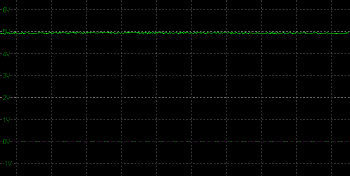  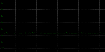 Brightness setting 100% 50% 0% |
| BenQ GW2760HS – W-LED backlight. At all brightness settings the luminance output is a flat line, showing no PWM is being used. This is part of BenQ’s flicker free range. |
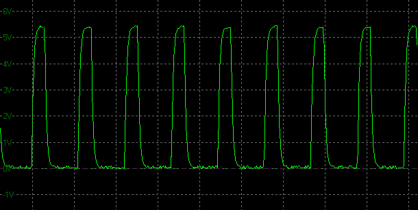
The oscilloscope graphs can also allow us to examine the behaviour of the luminance output. Above is a typical W-LED backlight dimmed to 0% where PWM is used. You can see the changes between on and off are very steep and sudden, as the LED backlight is able to turn on and off very rapidly. As we’ve already discussed this can lead to potentially more noticeable flicker and associated issues as the changes are more pronounced.

The oscillographs for a typical CCFL display using PWM at 0% looks like the above. You can see the transitions from on to off are less sudden as the phosphors don’t go dark as quickly as with LED backlight units. As a result, the use of PWM may be less problematic to users.
Conclusion
As we said at the beginning, this article is not designed to scare people away from modern LCD displays, rather to help inform people of this potential issue. With the growing popularity in W-LED backlit monitors it does seem to be causing more user complaints than older displays, and this is related to the PWM technique used and ultimately the type of backlight selected. Of course the problems which can potentially be caused by the use of PWM are not seen by everyone, and in fact I expect there are far more people who would never notice any of the symptoms than there are people who do. For those who do suffer from side effects including headaches and eye strain there is an explanation at least.
With the long term and proven success of a technology like Pulse Width Modulation, and the many years of use in CCFL displays we can’t see it being widely changed at any time soon to be honest, even with the popular move to W-LED backlit units. It is still a reliable method for controlling the backlight intensity and therefore offering a range of brightness adjustments which every user would want and need. Those who are concerned about its side effects or who have had problems with previous displays should try and consider the frequency of the PWM in their new display, or perhaps even try and find a screen where it is not used at all in backlight dimming. Some manufacturers are proactively addressing this concern through the use of flicker free backlights, and so options are emerging which do not use PWM.
| Support US | If you have enjoyed this article and found it useful, please consider making a small donation to the site. |